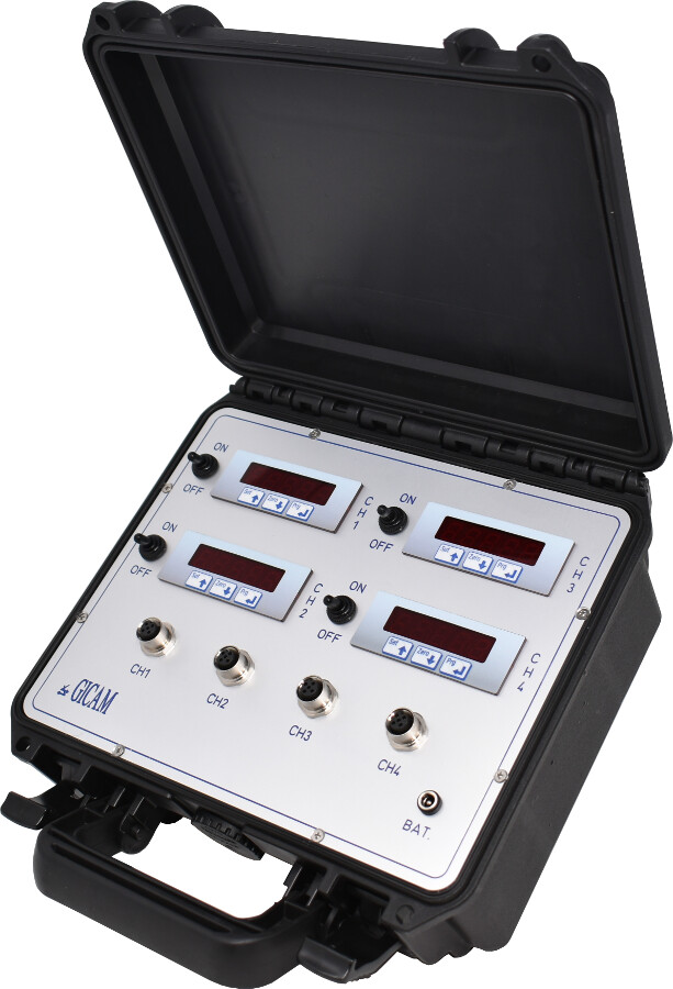
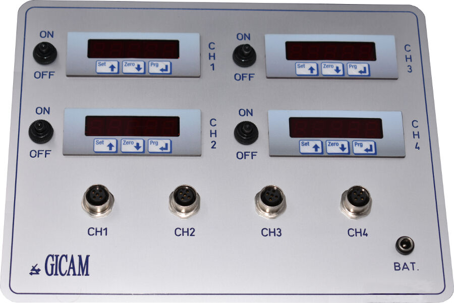
GICAM announced a new tool that further completes the range of portable indicators with independent power supply for displaying load cells with independent channels. The SLIM4C consists of 4 instruments that are able to display as many dedicated channels.
The 4 instruments are mounted in a practical case to be taken directly to the places where it is necessary to detect the reading of the load cells. It also has an independent power supply via rechargeable batteries and is complete with a battery charger.
A maximum of 2 350 Ohm load cells (or 4 700 Ohm cells) can be connected in parallel to each input channel.
![]() Click to enlarge image
Click to enlarge image


| Power supply | With batteries complete with charger | |
| Max power consumption | 1.5 W (each SLIM) | |
| Isolation | Class III | |
| Operating temperature | -10 / +50 °C (14 / 122 °F) Humidity Maximum 85% non-condensing | |
| Display | 5-digit numeric red 7-segment LEDs (h 10 mm) | |
| Keyboard | 3 mechanical keys | |
| Load cell input features | Maximum 2 cells of 350 Ω in parallel (or 4 cells of 700 Ω) | |
| Linearity | < 0.01% of full scale | |
| Temperature deviation | < 0.001% of full scale/C° | |
| Internal resolution | 24 bit | |
| Measuring range | From -3.9 mV/V to +3.9 mV/V | |
| Digital filter | 0.1 Hz - 50 Hz | |
| Number of weight decimals | From 0 to 3 decimals | |
| Zero / FS Calibration | Executable through buttons | |
| Cell cable interruption check | Always present | |
| Program code memory | 32 kByte | |
| Data memory | 2 kByte | |
| Conforms to standards | EN61000-6-2, EN61000-6-3, EN61010-1 | |
| Briefcase overall dimensions | 260 x 250 x 125 mm (10.2 x 9.8 x 4.9 in) | |
General precautions to be followed in the installation and assembly of load cells: